What is a Signal Isolator? Principle, Advantages, Disadvantages

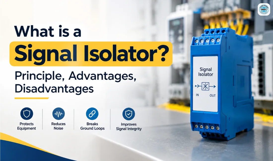
A Signal Isolator is an electronic device used in industrial automation and control systems to transfer electrical signals between two circuits while keeping them electrically separated. This separation is called galvanic isolation, where there is no direct conductive connection between the input and output circuits. Signal isolation is particularly useful when different devices have different ground references, when electrical noise affects measurement signals, or when sensitive control equipment needs protection from unwanted voltage disturbances. Signal Isolators are commonly used with 4-20 mA current signals, voltage signals, thermocouples, RTDs, PLCs, DCS systems, transmitters, sensors, and industrial measurement equipment. By separating the circuits, an isolator can help reduce ground loops, improve signal reliability, and prevent electrical interference from passing directly between connected devices. Depending on the design, a Signal Isolator may also provide signal conversion, filtering, amplification, or other signal-conditioning functions. In an industrial environment, field instruments can be installed far away from control panels and may operate under different electrical conditions. Motors, variable-frequency drives, contactors, power cables, switching equipment, and other electrical devices can also generate electromagnetic interference. A properly selected Signal Isolator provides an additional barrier between these circuits and helps maintain cleaner signal transmission.
How Does a Signal Isolator Work?
The working principle of a Signal Isolator is based on transferring signal information across an isolation barrier without allowing a direct electrical connection between the input and output. The input signal is detected and processed by the isolator, transferred through an isolation mechanism, and then reproduced at the output. The measurement information is therefore passed to the receiving equipment while the two electrical circuits remain separated. There are three common methods used for signal isolation: optical, magnetic, and capacitive isolation. Optical isolation uses light to transfer information. An LED converts the electrical signal into light, which travels across an insulating barrier and is detected by a photodetector on the other side. Since there is no direct electrical path between the LED and detector, the two circuits remain isolated. Magnetic isolation uses electromagnetic induction. A transformer or similar magnetic coupling arrangement transfers an AC or modulated signal between separated windings. The primary and secondary circuits remain electrically separate while the required signal information crosses the magnetic field. Capacitive isolation uses changing electric fields to transfer signal information through an insulating dielectric barrier. This method is particularly useful for high-speed or high-frequency signal applications. The choice of isolation technology depends on the signal type, operating frequency, required isolation level, accuracy, response time, and application requirements. For industrial analog signals, the isolator may receive a 4-20 mA input and generate an isolated 4-20 mA output. Some devices can also convert signals, such as 0-10 V input to 4-20 mA output. Other models are designed for thermocouples, RTDs, frequency signals, or other specialized inputs. The main purpose is not simply to change the signal. The important function is to separate the electrical circuits while preserving the useful signal information. This makes Signal Isolators valuable in applications where electrical interference, different ground potentials, or sensitive electronic equipment could otherwise cause problems.
Why is Signal Isolation Important in Industrial Systems?
Industrial control systems often connect several devices together, including field transmitters, sensors, PLCs, DCS controllers, displays, data acquisition equipment, and monitoring instruments. These devices may not share exactly the same ground potential. When their signal wiring creates an unwanted conductive path, circulating current can flow through the signal circuit. This condition is commonly known as a ground loop and can cause unstable readings, offsets, noise, or measurement errors. A Signal Isolator can break this unwanted conductive path. The field device can remain referenced to its own circuit while the PLC or controller receives an isolated version of the signal. Because there is no direct conductive connection through the isolation barrier, unwanted current caused by ground-potential differences can be significantly reduced. Signal isolation is particularly useful for 4-20 mA instrumentation. Current loops are widely used to transmit measurements such as pressure, temperature, flow, and level. If the transmitter and receiving equipment are located in different parts of a facility, differences in grounding can affect the signal circuit. An isolated signal path can help prevent these unwanted electrical interactions. Isolation can also provide an additional level of protection for sensitive electronic equipment. PLC input modules, monitoring systems, measurement instruments, and data acquisition hardware can be affected by electrical disturbances entering through connected signal wiring. An isolator separates the circuits and reduces the direct electrical path between them. However, a Signal Isolator should not be considered a replacement for correct electrical installation. Proper grounding, shielding, cable routing, earthing, surge protection, and equipment selection remain important. Isolation is one part of an overall strategy for maintaining reliable industrial signal transmission.
Advantages and Disadvantages of a Signal Isolator
A major advantage of a Signal Isolator is its ability to separate electrical circuits without losing the required measurement or control information. This makes it useful for industrial automation systems where field instruments and control equipment may have different electrical references. One of the most important benefits is ground loop elimination or reduction. By breaking the direct conductive connection between circuits, an isolator can prevent unwanted current caused by ground-potential differences. This can help improve the stability and accuracy of analog measurements. Another advantage is noise reduction. Industrial environments can contain significant electromagnetic interference from motors, drives, switching devices, power cables, and other equipment. Signal isolation can reduce the direct transfer of unwanted electrical disturbances between connected circuits. Signal Isolators can also provide equipment protection. Sensitive devices such as PLCs, DCS systems, data acquisition equipment, and measurement instruments benefit from electrical separation between field circuits and control circuits. The actual protection provided depends on the device’s isolation rating and other specifications. Many modern isolation modules also perform signal conditioning. Depending on the model, they can filter signals, convert signal ranges, amplify signals, or provide different input and output formats. This can simplify control-panel design and reduce the need for separate modules.
Key advantages include:
- Reduction of ground-loop problems.
- Improved signal integrity.
- Reduced impact of electrical noise.
- Electrical separation between field and control circuits.
- Additional protection for sensitive electronics.
- Signal conversion and conditioning in selected models.
- Support for different industrial analog signals.
- Improved reliability in electrically noisy environments.
Despite these benefits, Signal Isolators also have some limitations. Adding an isolator introduces another electronic device into the signal path. Depending on the product, this can introduce a small transmission error, offset, temperature drift, or response-time limitation. For high-precision applications, the manufacturer’s accuracy specifications should be carefully checked. Cost is another consideration. Installing additional isolation modules increases the overall hardware and panel requirements. Some active Signal Isolators also require an external power supply, which adds wiring and installation requirements. Bandwidth can also be limited depending on the isolation technology and product design. A device designed for slow industrial process signals may not be suitable for high-frequency applications. Therefore, users should always verify the required signal frequency and response time before installation.
Common disadvantages include:
- Additional equipment cost.
- Small signal transmission errors in some devices.
- Possible response-time limitations.
- Frequency or bandwidth restrictions.
- Additional wiring and panel space.
- External power requirements for some active models.
- Incorrect selection can cause signal compatibility issues.
Where are Signal Isolators Used and How Do You Choose One?
Signal Isolators are used across industrial automation, process control, manufacturing, instrumentation, energy systems, building automation, and measurement applications. They are particularly useful wherever electrical circuits need to communicate while remaining electrically separated. A common application is between a field transmitter and PLC analog input. For example, a pressure transmitter may produce a 4-20 mA signal representing process pressure. The signal can pass through an isolator before reaching the PLC. The isolator transfers the measurement while separating the transmitter circuit from the PLC input circuit. They are also used with temperature measurement systems. RTDs and thermocouples may require signal conditioning and isolation before their measurements are sent to a controller or monitoring system. Other applications include flow transmitters, level instruments, industrial sensors, data acquisition systems, process controllers, and monitoring equipment. Before selecting a Signal Isolator, the first requirement is to identify the input and output signal. Determine whether the system uses 4-20 mA, 0-20 mA, 0-10 V, thermocouple, RTD, frequency, or another signal. The output must be compatible with the receiving PLC, controller, display, or monitoring instrument. The isolation rating is also important. Check the manufacturer’s specified isolation voltage, test voltage, insulation characteristics, and applicable certifications. Accuracy, transmission error, temperature coefficient, response time, operating temperature, mounting arrangement, and channel configuration should also be considered. Power requirements must be checked carefully. Some Signal Isolators are loop-powered, while others require an auxiliary supply such as 24 V DC. The wiring arrangement should be confirmed before installation because active and passive signal configurations can differ.
A practical selection checklist includes:
- Input signal type and range.
- Output signal type and range.
- Required isolation rating.
- Accuracy and transmission error.
- Response time and bandwidth.
- Power supply requirements.
- Number of channels.
- Operating temperature.
- Panel mounting requirements.
- Required industrial certifications.
- Compatibility with PLC, DCS, sensor, or transmitter.
It is also important to understand the difference between a Signal Isolator and a Signal Conditioner. An isolator primarily provides electrical separation, while a signal conditioner modifies a signal through functions such as amplification, filtering, conversion, or linearisation. Many modern products combine both functions, providing isolation and signal conditioning in the same module. For example, a single device may accept a 0-10 V input, electrically isolate it, and provide a 4-20 mA output. This type of multifunction device can be useful when a sensor and PLC use different signal formats. For 4-20 mA applications, the user’s wiring arrangement should be checked carefully. The isolator must be compatible with the loop configuration, signal range, available power, and receiving input. Choosing a device only because it is labelled as a “4-20 mA isolator” may not be sufficient. A properly selected Signal Isolator can therefore provide both galvanic isolation and useful signal conditioning, but the final selection should always be based on the manufacturer’s technical datasheet and the actual requirements of the installation.
Conclusion
A Signal Isolator is an important component for reliable industrial signal transmission because it allows measurement and control information to pass between circuits without creating a direct electrical connection. Its galvanic isolation can help address ground loops, reduce unwanted electrical interference, separate different ground references, and provide an additional layer of protection for sensitive control equipment. Signal isolation can be achieved through optical, magnetic, or capacitive technologies, with each approach having different characteristics. In industrial automation, Signal Isolators are commonly used with 4-20 mA signals, PLCs, DCS systems, RTDs, thermocouples, transmitters, sensors, and process-control equipment. The correct product should always be selected according to the actual signal type, input and output range, isolation requirement, accuracy, response time, power supply, and environmental conditions. When correctly specified and installed, a Signal Isolator can help create a cleaner, more reliable connection between field instrumentation and control equipment. For industrial electrical and automation requirements, you can explore Aarcee Electrical Controls and its range of industrial products at aarceeelectrical.com. Always refer to the relevant manufacturer’s datasheet before installing a Signal Isolator in a control or measurement system.
FAQs
Have questions? We’ve answered some of the most common queries to help you understand the topic better.
Q1. What is a Signal Isolator?
A Signal Isolator transfers electrical signal information between two circuits while keeping them electrically separated through galvanic isolation.
Q2. What is a Signal Isolator used for?
It is mainly used to reduce ground loops, improve signal integrity, provide electrical separation, and protect sensitive control equipment.
Q3. Can a Signal Isolator be used with 4-20 mA?
Yes. Many industrial Signal Isolators are designed specifically for 4-20 mA and 0-20 mA current signals.
Q4. Does a Signal Isolator reduce electrical noise?
It can reduce the transfer of unwanted electrical interference between isolated circuits and can improve signal reliability in noisy industrial environments.
Q5. How do I choose a Signal Isolator?
Check the input and output signal, isolation rating, accuracy, response time, power requirement, operating environment, and compatibility with the connected equipment.